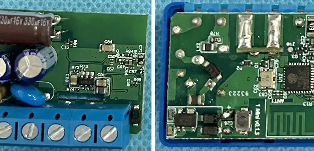
As an embedded engineer, I often find myself fighting against physics. In the smart home industry, the biggest adversary isn’t software bugs or connectivity issues—it is the physical lack of space.
We have all been there. You open a wall switch box to install a smart relay, only to find a chaotic nest of stiff copper wires, wire nuts, and practically zero depth. Standard relays simply don’t fit without aggressive (and often dangerous) force.
This is why the Shelly 1 Mini Gen3 is such a fascinating case study. It claims to be the smallest relay in the world. But shrinking a high-voltage device isn’t just about making things smaller; it requires a complete rethink of component density and safety margins.
Today, we are looking at the engineering decisions behind this 29mm device. Based on the FCC filing (ID: 2BDC6-1MINI) and internal specs, here is what makes this tiny relay tick.
The PCB & Size – Achieving Extreme Density
The dimensions of the Shelly 1 Mini Gen3 are 29x35mm. To put that in perspective, it is barely larger than a standard coin.
In the world of 5V DC electronics, miniaturization is common. But this device handles mains voltage (110V - 240V AC). This presents a massive engineering challenge known as “The Art of Density.”
The primary constraint here is safety regulations regarding Creepage and Clearance. You cannot simply place a high-voltage AC trace next to a low-voltage DC logic line (like the GPIO pins for the switch). If the gap is too small, electricity can arc across the PCB, destroying the microcontroller and potentially causing a fire.
Shelly’s engineering team managed to utilize the “dead space” inside the switch box by optimizing the PCB artwork. They maintained the necessary isolation distances while packing components tightly. Another subtle but critical improvement is the terminal design. In previous mini-relays, small terminals often meant loose wires. The Gen3 uses a robust clamping mechanism that grips wires securely despite the reduced footprint.
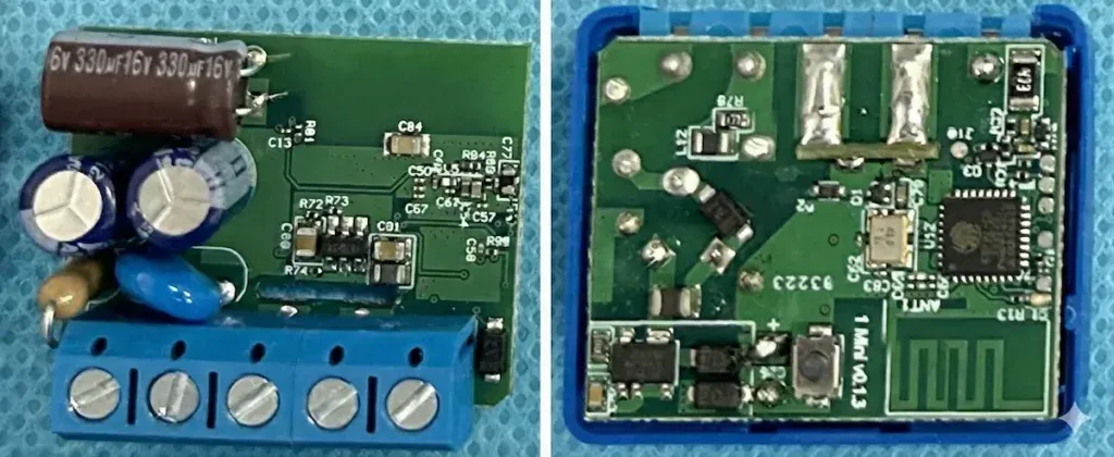
Extreme Density: Maintaining safe creepage distances in a crowded PCB is an engineering victory.(Source: FCCID.io)
Unlike the [Aqara Climate Sensor W100] which focuses on minimalist efficiency, the Shelly 1 Mini is a masterpiece of extreme component density.
The Brain – Why They Used the Custom ESP-Shelly-C38F
When you look at the board, you won’t find a generic ESP32 module. Instead, Shelly has deployed a custom System on Chip (SoC) labeled ESP-Shelly-C38F.
Why go through the expense of a custom silicon solution? The answer lies in optimization and future-proofing.
1. GPIO Optimization
A standard ESP32 package has many pins that a simple relay doesn’t need. By using a custom package, Shelly can route only the necessary GPIOs, saving valuable millimeters on the PCB footprint.
2. The 8MB Flash Advantage
This is the most critical spec. The C38F chip comes with 8MB of Flash memory. Competitors often cut costs by using 2MB or 4MB chips. However, in 2026, the Matter protocol has become the industry standard, and it is “heavy” in terms of code size.
Furthermore, to perform safe Over-The-Air (OTA) updates, a device needs an “A/B partition” structure—essentially needing enough space to hold both the current firmware and the new update simultaneously. By providing 8MB, Shelly is ensuring that this device won’t become e-waste in a year or two. It has the headroom to handle future protocol updates that heavier, cheaper devices cannot.
Regulatory Insight – The FCC ID Strategy
Interestingly, looking up the regulatory information reveals that the Shelly 1 Mini Gen3 operates under FCC ID: 2BDC6-1MINI.
This is the same ID used for the “Plus 1 Mini”. Engineering Insight: This suggests that despite the “Gen3” branding and the new C38F chip, the RF (Radio Frequency) section of the PCB design remained electrically similar enough to the previous generation to pass as a “Permissive Change” or variant. This is a smart move to reduce certification costs and time-to-market, allowing Shelly to iterate faster than competitors who must re-certify every minor board spin.
Thermals & Limits – The Necessary Engineering Trade-off
Engineering is never about perfect solutions; it is about managing trade-offs. The Shelly 1 Mini Gen3 makes a clear compromise to achieve its size.
The Problem: Power electronics generate heat. The Usual Solution: Large aluminum heatsinks or air gaps for convection. The Mini’s Reality: There is zero space for heatsinks.
Because the device physically cannot dissipate the heat generated by a high current load, Shelly has limited the output to 8A. For comparison, the larger “Plus” or “Pro” series relays often handle 16A.
This 8A limit is a physical necessity. Pushing 16A through such a small PCB trace without a heatsink would melt the casing. To manage this, the device relies heavily on software safety. The ESP-Shelly-C38F runs a continuous Over-temperature protection algorithm. If the internal sensor detects a breach in the thermal envelope—perhaps due to a resistive load heating up the terminals—the firmware cuts the power immediately.
Verdict – Is This the Best Relay for Tight Spaces?
The Shelly 1 Mini Gen3 is a specialized tool. It is not a “do-it-all” device, but a problem solver for specific scenarios.
You should choose the Mini if:
-
You are retrofitting crowded US or European wall boxes.
-
You are controlling lights or small fans (loads well under 8A).
-
Depth is your primary constraint.
You should choose the ‘Plus’ version if:
-
You need to control space heaters, heavy pumps, or entire circuits (up to 16A).
-
You require power metering (Check the PM Mini Gen3 for this feature).
-
You have plenty of space in the wall box.
In conclusion, the Shelly 1 Mini Gen3 is a victory of PCB layout and component selection. It proves that with the right custom silicon and strict thermal management, we can make smart homes invisible.
(Disclaimer: This teardown is based on technical specifications and public regulatory filings. Always consult a licensed electrician when working with mains voltage.)